
Note: This page is being offered as additional reference and alternate methods for building a stern thruster pod for a Pilgrim 40 or similar vessel with a raised transom with soft chines. The original pod was engineered, built and installed by Dave Forsman and it is suggested that if you have not reviewed his 2-piece layup process and details that you visit the page now before proceeding. The choice of method is up to you. You may also like to familiarize yourself with Dave’s pre-planning thoughts and processes that you can read about here.
As Dave said on his page, “In reality this page was created to document the processes for my own benefit as well as a guide for anybody foolish enough to want to do it themselves.” Count me among the fools.
First, it helps to know what we are striving for. Courtesy of Dave and lifted off of Liberty’s project page, here is his original sketch for the placement of the thruster mounting pod.

The process of fiberglass layup was a throw back to my time as a student of industrial design student in the 70’s. If it wasn’t for this past experience I may have walked away without attempting the thruster pod project. The difference between now and then is that the hard work of making the plug and laying up the molds was done. This scale model sailboat hull was the outcome of my mold-making education.

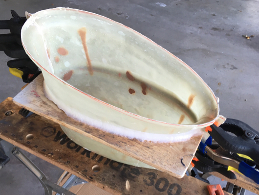
Because of the experience of laying up the boat hull in one piece I decided to do the same with the two-piece thruster mold. To assure seams were tight I clamped the entire bottom joint in a Workmate table and lined the end seams with as many clamps that would fit.
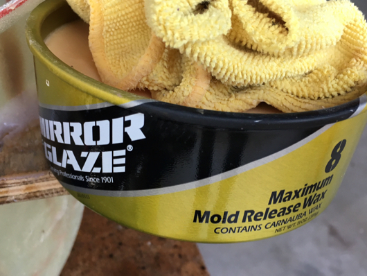
The inside surfaces were buttered up with five coats of Maguires Mold Release Wax.
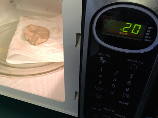
To fill the seams in the leading and trailing edge of the mold I used “Chavant Le Beau Touche Clay” which comes in a 2 lb. block. Being that a chill is in the air I microwaved a chunk for 20 seconds to make it more pliable to assure it would work deep into the seam.
The seam is well filled and smoothed to blend into the waxed sides.

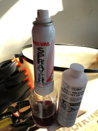
Because the top edge of the mold was rough and porrous I didn’t want to take any chances that the fiberglass would grab and not let go. A simple band of vinyl electrical tape was used to cap the edge. Next up was spraying on PVA (Poly Vinyl Alchol) mold release, first a light misting coat followed up by a wetter coat.
Polyester gel coat was applied by brush and allowed to set enough to become tacky so that a chemical bond could be provided between the resin that was going to follow it.

First up was a layer of 1-1/2 oz chopped strand fiberglass mat to be alternated every couple of layers by a layer of 6 oz/sq yd fabric roving. It was decided that at least the outer few layers would be layed up using vinylester resin because of it’s resistance to impact, cracking and blisters. The trade off was it’s high cost so the rest of the layers would be switched over to polyester resin.

To come up with a shell that would be close to 3/16″ it was calculated that 9 layers would need to be cut.
|
All fabric was cut beforehand so that the layup process wouldn’t become stalled. Since the layup was going to be in a confined space separate pieces were cut for the bottom and various width for sides. It was becoming apparent that the one-piece approach was going to be quite a bit more time-consuming during layup, and probably long enough to exceed the time it would take of later joining two halves at the seams, but I was committed.

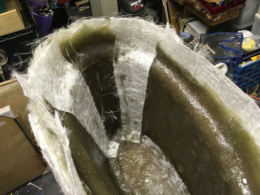
Larger pieces of mat were suitable for the sides without fighting the form…
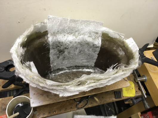
…while narrower strips were used for the ends. The overlaps of the strips were staggered and created little stringers that added to the structural integrity.
The pod was completed using 1 quart of vinylester resin for the first three layers followed up with 2-1/2 quarts of polyester resin.

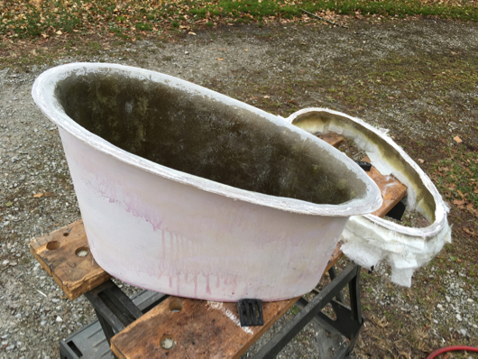
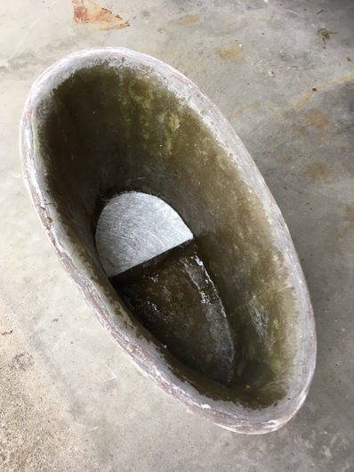
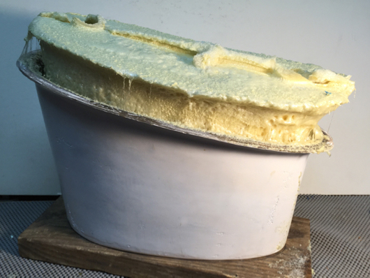
The scary part was next… pulling the mold apart. All behaved like it should and the toche clay, seen on the edge of the pod in the photo, did it’s job protecting the seam. It’ll be washed off along with the pinkish cast that PVA left on the walls of the pod.

Time for a hair cut. The Fein Multi Master tool came in to play to make a clean cut around the top edge.
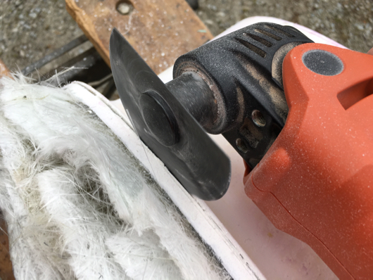
Nice!
To prepare for the extension tube that will pass from the thruster to inside the boat hull a stiffening pad needed to be made to accomodate an elastomer sealing ring. Since there was still leftover stranded matt about 30 blanks were used until either they, or the leftover 1/2 quart of resin, was used up. It turned out be excessive with a resulting 1-1/4″ thickness. It was planned to use a 1/2″ elastomer ring but with the added thickness a 1″ ring will be used.
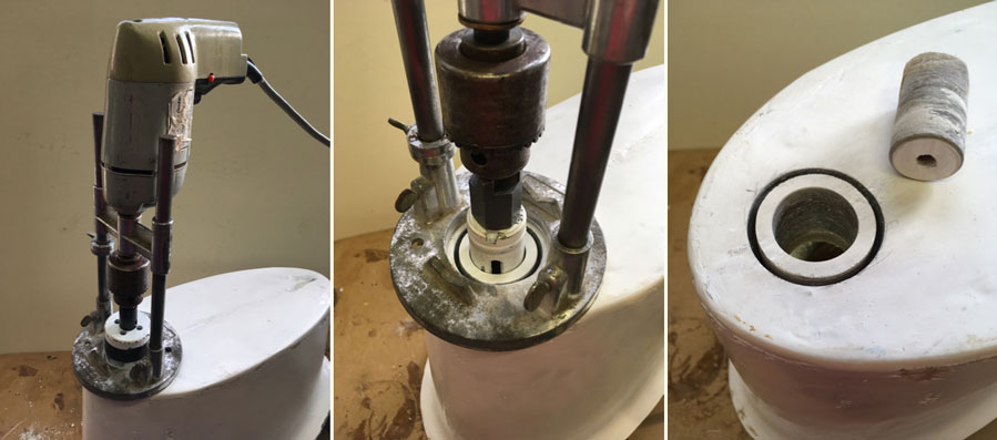
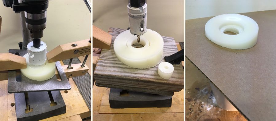
A floor drill press wasn’t available to assure a true hole-through so a poor man’s drill press came into action. An alternate, and no doubt truer, process would be to use Dave’s locating pin and routing fixture to create the counter bore. You should read about it to make a informed decision before proceeding.
First a 2″ diameter hole was drilled 3/4″ deep. This will allow a 1″ elastomer sealing ring to be used since it requires an undersize depth of 25% that will be compressed during mounting of the thruster.
Using the center hole left by the 2″ circular bit a 1-1/4″ hole was bored completely through the pod.
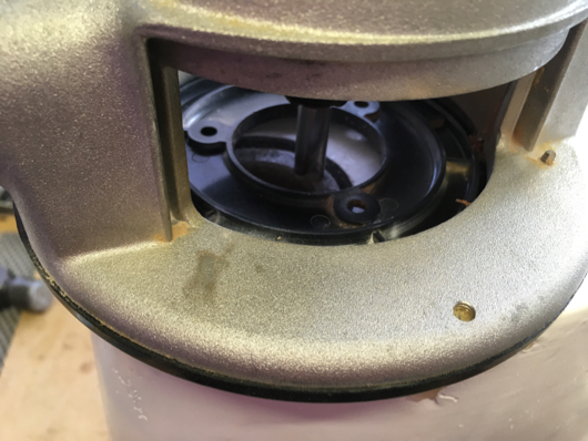
The router came into action to cut out the waste between the two holes, set to counterbore 3/4″ deep to the bottom of the 2″ diameter hole. To assure that the bit didn’t nick the outer wall a thin strip of metal was cut from a soda can and inserted in to the gap. This risk wouldn’t have been there using Dave’s routing fixture and top-bearing flush cut bit.
The finished counter bore of the 2″ outer hole and 1-1/4″ thru-hole for the extension tube.

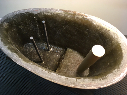
A length of 1-1/4″ Schedule 40 PVC pipe will be used as the pass-thru for the extension tube. Dave talked about using fixture to assist with accurately lining up the PVC pipe, along with the threaded rods, so they passed through the pod true during the foaming process. There wasn’t any pictoral reference as to what his fixture looked like when he built his piano… I mean pod… so I made up one that would seem to do the job.

The pod sitting on the fixture looking ready for the PVC pipe and foaming.
The inside diameter of the PVC pipe is larger than the outside diamer of the 1-1/4″ dowl so to keep the dowl centered it was wrapped with blue painters tape. This was done both at the bottom and top until there was a snug fit when the PVC pipe was placed over it. The PVC pipe was slid on over the dowl and was epoxied in place
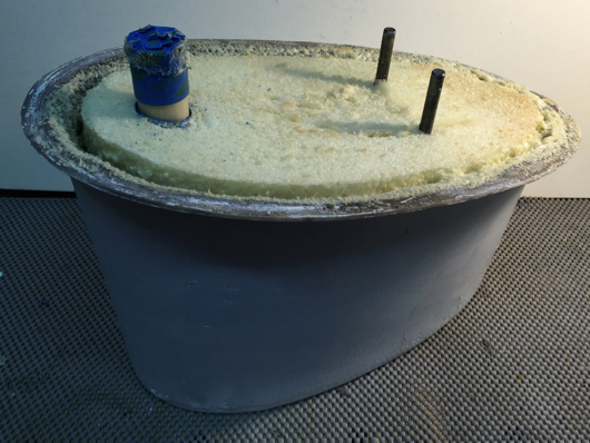
In spite of trying to carefully calculate the amount of “mix & pour” foam that would be required it got out of hand. The plan was to do two pourings but the second pour never came about. Okay, you can stop laughing now.
No matter since the foam is easily cut down with a hand saw. The gap that was left around the perimeter will be cleaned out and sanded. When it comes time to attach the pod to the hull it’ll be filled with thickened epoxy to add to the bonding properties.
Knowing that some wedges would be needed for inside the hull, silca-thickened epoxy was poured into caps and allowed to self-level. The caps shown here are from the top of a quart can of VC-17 bottom paint and the top of a quart can of polyester resin.
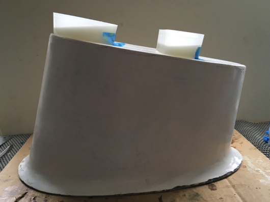
The wedges popped out from their molds and look to be just about right for being parallel with the bottom where the thruster will mount. Be sure to check Dave’s page to see how he made his wedges with marine plywood.

Here’s a bit of Déjà vu. The wedge that will serve as the backing plate for the extension tube gets the same treatment as the bottom of the thruster pod. In this case a benchtop drill press was used to align the circle cutters, first the 2″D cutter was used that went down 3/8″ to accomodate a 1/2″ elastomer ring (less 25%) and then the 1-1/4″ cutter that passed completely through.
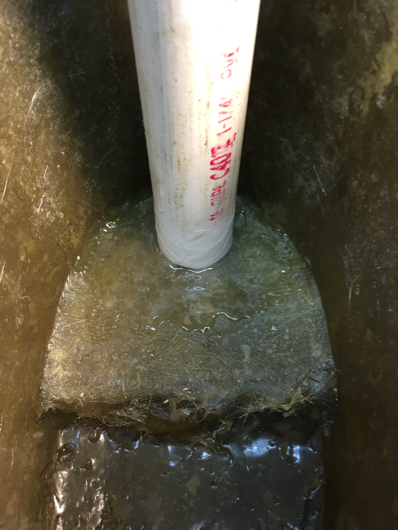
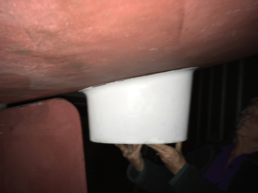
There’s not much more to do while waiting for the thruster arrive and the weather to get warm. A quick trip was made to the boat yard to shake out some anxiety by checking the fit. So far, so good.
Click here to about Part 2 of the installation.